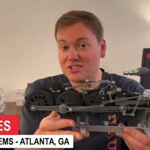
In the world of hobby engineering and model making, nothing quite matches the thrill of seeing your own creation come to life. Today, I’ll be sharing the journey of testing my 3D printed locomotive model using compressed air—a venture fueled by both persistence and a touch of engineering acumen.
Setting the Stage
With a trusty two-gallon portable compressor on standby, I embarked on testing the system. Handling this setup with just two hands proved tricky due to the rigidity of the hose. Blocking off the other airport and ensuring that the assembly flexed to avoid binding were crucial tasks. Despite the challenges, the locomotive ran, bringing an enormous sense of relief.
The Initial Challenges
The journey wasn’t without its stumbling blocks. The locomotive system required precise setup: the piston needed to be positioned accurately, and a quick burst of air was often necessary to get it running reliably. The system was unpredictable, with the wheels mostly just rotating an eighth to a quarter of a turn before stopping. This inconsistency gave rise to doubts about potential design flaws, particularly concerning the valve piston blocking the steam admission ports.
Diagnosing the Issue
To resolve this, I revisited educational videos on steam locomotive mechanics. Crucially, I realized that steam locomotive drive wheels are quartered—meaning the crank on one side is shifted 90 degrees from the other. This design prevents the issue I was encountering by ensuring the valve piston always admits steam on one side of the train.
Moving Forward
Knowing this, I concluded that the solution lay in constructing the other half of the locomotive. To keep you, the reader, engaged, I’ll speed through this part: I printed all the necessary additional parts, including the mirrored components. Machine keys were inserted into the drive wheel axles to achieve the quartering, and I then joined the other half of the partially assembled chassis.
Reassembly and Optimization
I redesigned the piping network and attached it to the cylinders after rethreading an NPT coupler into a newly printed resin part. As you may notice, the assembly was placed on a stand I designed and printed off-camera. Although the setup was rolling smoothly, some friction persisted, so I applied silicon lubricant generously across key areas to mitigate this.
Final Testing and Success
With everything assembled, I switched to a lighter gauge hose for testing. Once I started pumping in air, the model worked perfectly. The satisfaction was immense, as potential mechanical errors introduced by the physical world could have easily derailed the project.
After a successful full-throttle forward test, I manipulated the radius rod to simulate reverse movement. With a quick burst of air, the locomotive model fired into reverse, validating the setup of the valve gear.
Conclusion
This endeavor highlights the intricate dance between design and functionality in the realm of model making. Each test, challenge, and eventual triumph reflects not only the complexities of engineering but also the boundless joy of turning a digital dream into physical reality. Keep tinkering, designing, and above all, enjoying the process.
Check out part two of this series: Fixing the Big Boy 3D Printed Drive: Design Iterations, Linked Reverser, and a Track Test
More in this Locomotive Webinar Recap
-
-
- Designing a 3D-Printed Steam Engine You Can Power With Compressed Air (Big Boy Inspiration)
- Designing Working Walschaerts Valve Gear in SOLIDWORKS: Validating Link Lengths, Lap & Lead
- Choosing FDM vs SLA for a 3D Printed Model: Stand Design, Part Planning, and Hardware Prep
- Crafting a G-Scale Replica: Designing the Iconic Big Boy Locomotive
- Designing and Testing Linkages in SOLIDWORKS: Clearances, Mates, and 3D-Printed Fit Checks
- Assembling a 3D-Printed Steam Engine Valve Gear: Fits, Clearances, and Iteration
- Why My 3D-Printed Steam Locomotive Kept Stalling (And How Quartering Fixed It)
-