Eliminating Gaps to Improve Cycle Times in Mastercam
What is a Gap?
In Mastercam, a Gap is an area of “Air,” either outside of the material or a previously machined area. The amount of “Air” can be specified as either a “Distance,” or as a “Percentage of the tool diameter.”
How you transition through the “Gap” can be an important factor in cycle time, provided the setting for the “Gap size” distance is set properly based on the machine tools’ ability to “Accelerate” and “Decelerate” the mass of the table, part, and all of the fixturing components.
Acceleration and deceleration control is essential to control functions in CNC systems. It has a significant impact on the system’s accuracy and performance. In high-speed machining, acceleration and deceleration control is particularly important.
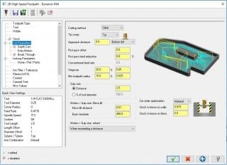
In the below example of the “Dynamic Mill” toolpath, “Cut Parameters, the “Gap size” is set to “Distance.” This distance is the number of inches that it takes for the machine tool to move, in rapid, to obtain its maximum rapid capability from a complete stop and then decelerate to a complete stop. This number is specific to your machine tool. In this example, it is set to 3.5”.
Gap Size: Distance
If the distance from the end of one pass to the start of the next pass is less than this distance, (Motion < Gap size, Micro lift) Mastercam does not create a retract move as defined on the Linking parameters page. Instead, the tool stays on the surface, or as defined in the “Micro lift” parameters, and moves directly between the passes at the feed rate.
Gap Size: Percentage of Tool Diameter
If the distance from the end of one pass to the start of the next pass is less than this distance, defined as a percent of the tool diameter, (Motion < Gap size, Micro lift) Mastercam does not create a retract move as defined on the Linking page. Instead, the tool stays on the surface, or as defined in the “Micro lift” parameters, and moves directly between the passes at the feed rate.
In the diagram below, the Gap size Motion or “Distance” is less than the machine tool’s ability to obtain its maximum rapid capability. In this case, we will want Mastercam to “Micro lift,” as this would be faster than going into rapid up to the retract height, over to the new start point, then down to the cut depth.
Back Feedrate
This controls the speed (inches per minute or millimeters per minute) of the tool’s backfeed movement. This allows 3D arcs between cuts to have a different feed rate than the rest of the toolpath, which can help reduce cycle time.
Motion > Gap size, Retract
In the diagram below, the Gap size Motion or “Distance” is greater than the machine tool’s ability to obtain its maximum rapid capability. In this case, we will want Mastercam to rapid up to the retract height, over to the new start point, then down to the cut depth, as this would be faster.
This drop-down menu controls the retracts in the toolpath when making a non-cutting move within an area where the tool can be kept down or “Micro-lifted”. Choose one of the following options:
• Never: Eliminates retracts from the toolpath for these types of tool moves.
• Avoiding a boundary: Adds retracts to avoid intersecting boundaries (a gouge boundary, or a boundary of material yet to be milled). The types of boundaries that Mastercam detects and avoids include chained geometry, part features, and stock.
• Exceeding a distance: Adds retracts when the next cut pass begins at a distance that is greater than the distance you define, either as an absolute Distance or as a pecentage of tool diameter. The distance is the allowable length of the down or “Micro-lifted” move.
Note: Choose options that include Boolean expressions (OR/AND) to customize further retract moves for your application.
Some of the “Classic” toolpaths such as the “Surface Finish Parallel,” use the “Finish parallel parameters,” “Gap settings…” to control how the tool reacts outside of the selected “Drive surfaces,” as shown below.
About the author
George has been an Applications Experts with MLC CAD Systems for more than 14 years. He brings real Machine Shop experience to the table with previous experience as an Applications Engineer for a Machine Tool Distributor in North Texas and over 20 years as a Machinist on the shop floor. Along with being an ASQ Certified Mechanical Inspector since 1987, he understands that at the end of the day, we are ultimately judged by our ability to measure what we did.